Defining the Threat Model for Embedded Systems (Part 2): Where Do you Need Security?

In Part One, we focused on identifying what data needs to be secured in your system. In this part, we will consider where our applications and data reside, so we can make sure any applied protections are meeting the desired goal. Identifying where our applications and data reside is critical to protecting it at rest, runtime and in transit. Similarly, an attacker or reverse engineer follows a nearly identical process to identify where the applications or data are located to focus their efforts and achieve their goals, whatever they may be. The identification of where an application or data resides and the threat model, can be used to help ensure adequate, holistic protections are applied across the entire system boundary.
Unlike the system designer, a reverse engineer or attacker will likely approach attacking a system differently depending on whether they have physical access to the device, or whether they only have logical, over-the-wire access. As a system designer, we use these decisions to help control our threat model and implement various protection mechanisms, based on the threats we are trying to protect against. Similarly, an attacker must understand the risks associated with various attacks – do they only have one device to work with, or many? As a system designer, we make very similar tradeoffs based on the value of the applications or data we’re protecting and what the threat model is. Finally, the attacker may string together many intermediate steps to achieve his/her final objective. These intermediate steps could include subverting trusted boot mechanisms, bypassing memory integrity verification mechanisms, arbitrary code execution, and privilege escalation. This alone is why we as system designers need to consider applying defense in depth and not relying on a single security solution. Security is not a solution, it’s a process with lots of thought and design considerations required.
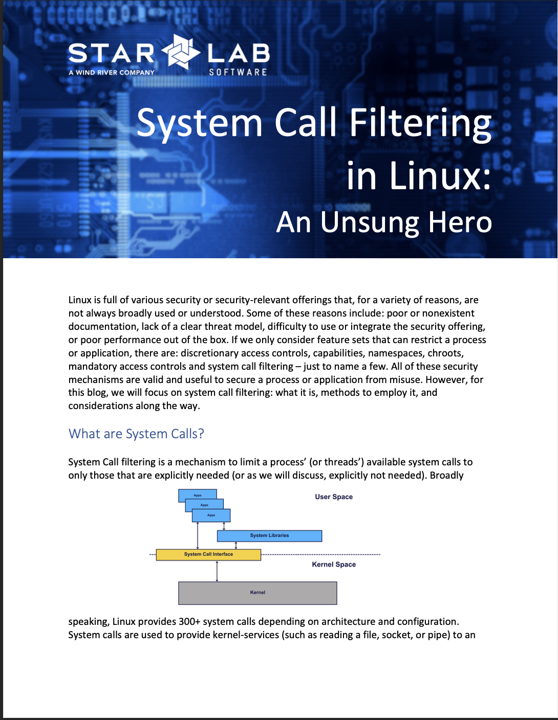
What is System Containerization?
What is system containerization? Here, we use the phrase container to describe the specific location of applications and or data; this is not the same as Docker or Kubernetes. However, that is not say that container engines such as Docker or Kubernetes can’t be used to isolate, contain, and protect specific applications or data. Our use of containers here could be thought of similar to a nesting doll, not a specific container or orchestration engine. Now that we’ve defined container, we’ll walk through a systematic approach to reverse engineering (and system design), in which the system is decomposed into one or more nested containers. These containers can then be attacked or conversely, defended, individually or sequentially to achieve a specified goal on the system. It may be necessary to gain access to a lower container, to perform an attack on a higher-level container, and similarly our threat model may enable us to ignore lower-level containers, as they are considered acceptable given cost targets and the value of the applications and data we’re protecting. Similarly, an attack on a higher container, may enable an attacker to have access to a lower container, or to mitigate the need to go after a lower container. All of these are considered, as we apply defense in depth and design our system.
As an example, let’s consider a notional system and goal. Our goal is to review message history and contacts on a powered-off mobile device running Android. For this scenario, we will assume the following:
The user’s data is encrypted at rest and protected with a password derived from biometric information (i.e. a fingerprint).
The biometric data is converted to a password within TrustZone.
The user’s data is only decrypted when the user is actively logged into the device.
The mobile device uses a trusted boot mechanism to protect the OS and baseband processor.
We have physical access to the mobile device.
This notional example is representative of most real-world systems and can be used to show how we can apply defenses at various layers of the system.
Decomposing the System into Containers
Reverse engineering a system requires that the system be decomposed into one or more containers to guide the attacks and reverse engineering process. Similar to a system designer’s point of view, we need to decompose our system such that we can identify where specific security mechanisms or defenses should be implemented. As mentioned above, attacks and successful exploitation of one container may mitigate the need to attack or exploit a different container. The attacker’s goal(s) lie within one or more containers, and they must defeat at least that (or a lower-level) container’s defenses to achieve their goals. Together, the containers represent the system and the layered approach to security that must be defeated to achieve attacker goals.
Containers can be physical or virtual and represent various facets of the system. The more granular the container breakdown, the easier it is to identify attacks that accomplish the attacker’s goals and the more flexibility may be employed for defense in depth as a system designer.
Using our notional platform from above, we can identify the following containers within the mobile device:

Using this model, if the attacker can directly exploit the Contacts Application, there is no need to access the Application Sandbox.
So how would an attacker directly exploit the Contacts Application? The opportunities are endless, but they could include system libraries such as those used for parsing JSON, XML, or SQLite databases. The attack vectors could include arbitrary code execution within the context of the application because of a heap overflow, ROP, unbounded copies, etc. We can defend against this using ASLR, stack canaries, type safe languages, and secure supply chain including a thorough vetting of all libraries and code within our application and all its dependencies. A single point solution will not address the myriad of potential vulnerabilities within an application or its dependent libraries.
Conversely, from within the Contacts Application and its sandbox, the attacker is prevented from updating system flash or manipulating TrustZone. This of course assumes we have implemented proper mandatory access controls, reduced the overall attack surface, and removed unnecessary permissions, capabilities, and access from the application sandbox. Further, if an attacker can gain control over TrustZone, they can interact with the application, its sandbox, and the rest of the system, not to mention potentially subverting secure boot mechanisms and accessing the system keystore(s). We can defend against this by extending our same protections to TrustZone (e.g., using type safe languages, removing attack surface, separating applications, etc.). Similarly, it should be evident why we need to integrate TrustZone with our secure boot process and ensure that secure boot is backed by hardware.
On our notional system, where we also want to integrate TrustZone into our secure boot environment, we might have something that looks like this:
Power-on Reset -> Starts executing from Masked ROM.
Masked ROM then uses a public key hash stored in Mask ROM to verify the public key stored with the TrustZone firmware (in SPI flash).
Using the now validated public key, Mask ROM verifies the integrity and authenticity of the TrustZone firmware from SPI flash.
TrustZone is loaded into main memory and execution is transferred to it
Once started up in a limited, secure mode (i.e. hardware-level access bits for TrustZone), TrustZone loads u-boot from flash and verifies it using another verified public key (rooted in hardware).
Note: While not specifically mentioned here, TrustZone needs to be limited to only executing properly authenticated applications and libraries. This could take the form of a read-only firmware and something like allowlisting within the TrustZone kernel. In most implementations, TrustZone is a mini-OS, complete with its own kernel, application set, libraries, and data. Everything that we would normally use in the host-OS for a security measure should at least be evaluated for use within the context of TrustZone.
U-boot then verifies (i.e., authenticates and validates integrity) the kernel, root file system, etc. The keys and/or hashes used by uboot could be located within another authenticated source, hardware, battery backed RAM, etc. This is all determined by what is available on the platform and our overall threat model.
As the guest kernel starts, we validate (both authenticity and integrity) our application sandboxes.
Using the container breakdown of the system, the attacker can target attacks (and/or reverse engineering efforts) at the component(s) of the system that will provide the most bang for the buck relative to their goals. Similarly, as a system designer, we should choose where to focus our efforts. In most systems, we can probably accept the threat model as force physical access, so we can move threats such as introspection system memory, snooping a bus, etc. outside of scope. This same level of threat model identification exists within the FIPS 140-2 standards, with the difference between a Level 1 and Level 4 module. Breaking down the system and our applications / data into their basic container building blocks enables us to determine where and how we implement various aspects of security on order to have a more secure system, protected from a variety of attacks. On a system where we’re primarily concerned with preventing logical over the wire attacks (i.e., ransomware, general malware, botnets, theft of patient data, etc.) we can use our system decomposition to identify the boundaries of protection and narrow our threat model. Similarly, if we have a system such as autonomous driving with a different threat model, maybe one where we are very concerned with physical access and bus introspection, our container decomposition may lead us to include a variety of physical controls on the system (i.e., tamper evident seals, sealed enclosures, buried traces, etc.).
A typical container breakdown is show below. Not every system or device will have all the possible containers. Other containers outside of these also exist and are highly dependent on your specific application and threat model.
Hardware Containers
System-of-Systems (i.e., air traffic control, cloud infrastructure, etc.)
Platform (i.e., aircraft, vehicle, Xbox, mobile device, etc.)
Sub-system (i.e., signal processing cabinet, data storage center, etc.)
Box (i.e., rack of equipment, stand-alone chassis, 1/2/3U server box)
Board (i.e., single-board computer, peripheral card, I/O board)
Component (i.e., CPU, ASIC, FPGA, flash, bus)
Sub-component (i.e., memory cell, trace, logic unit)
Software Containers
Firmware (i.e., BIOS, management firmware, microcode, FPGA, TrustZone)
Hypervisor (if present)
Operating System Kernel (Linux, VxWorks, Android, Windows, device drivers)
Files (binaries, libraries, scripts, data files)
Process environment (i.e., jvm, native application, python, namespace, sandbox)
Application (Python script, Java application, etc.)
This exercise was only a brief glimpse into system containerization, primarily as a mechanism to demonstrate assessing where data and applications reside in order to implement security solutions appropriately. Depending on the system and the requirements levied on the system designers, this process can become quite granular. There’s no way to thwart every possible attack, but this systematic approach should help ensure a system designer has the right information to make the best decisions about where to put protections in place.
To find out more about securing your data and applications, check out the following resources: